
Steel Truss Robotic Welding Lines
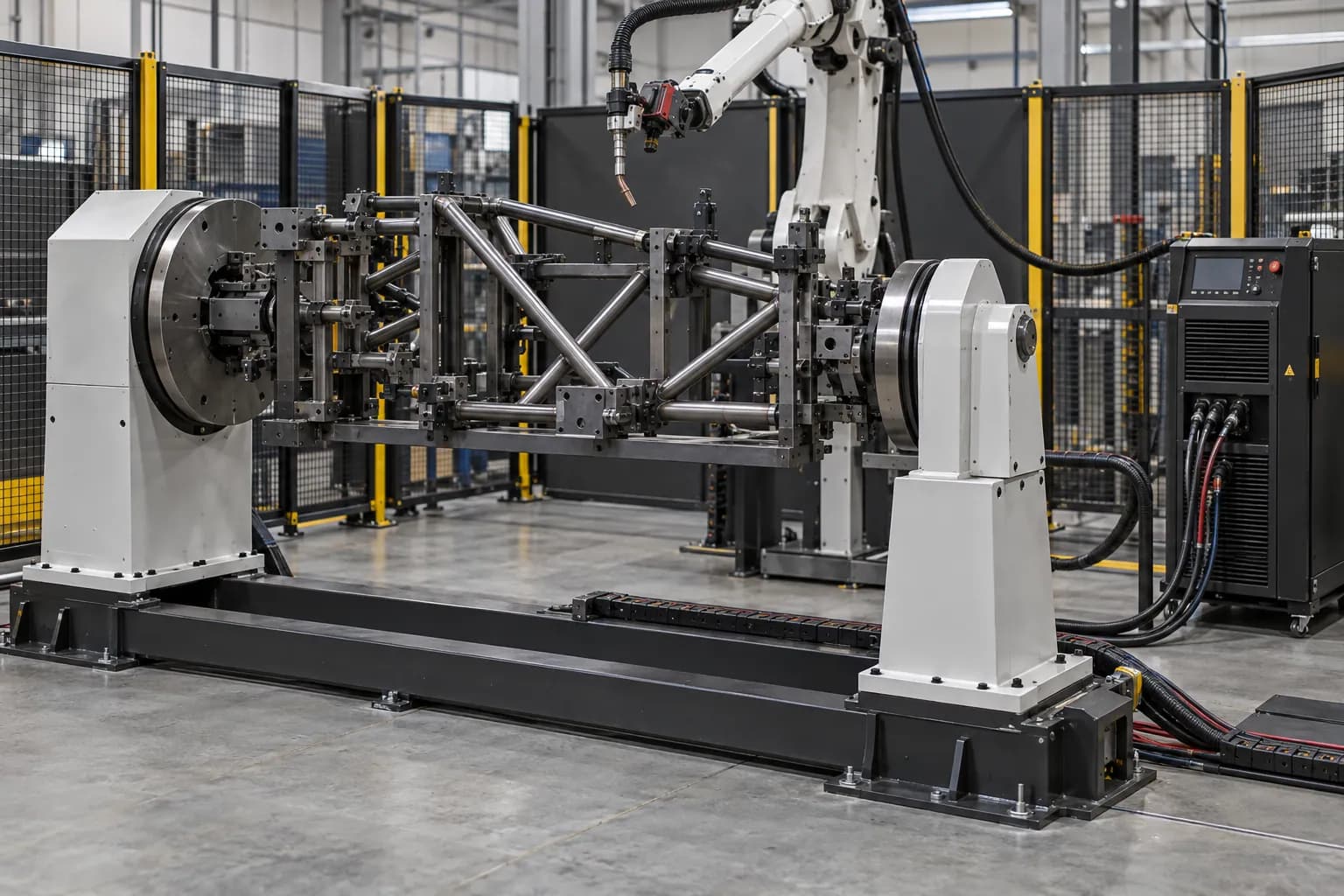
Steel truss robotic welding lines combine long-part support, joint fixtures and robot travel for tubular trusses or Bailey-panel-style lattice assemblies. The layout follows node geometry, member variation and the access needed to weld and unload the complete assembly.
- Model options
- 2
- Compare by
- Layout, torch access and process
Torch access and welding configuration
Identify every chord-to-brace joint and the clamps near it. Define tack condition, weld sequence, support positions and dimensional inspection after unclamping. A long rail does not by itself solve access to the far side of a node or control weld distortion.
A welding robot supplies motion; the weld is produced by the complete process package. Match the torch, feeder, power source, wire and shielding gas to the joint and material. Check the torch angle and distance at every seam, including clamps, corners and the path between joints. Fixture repeatability and incoming fit-up determine how consistently the robot meets the joint. Where variation requires sensing, specify whether the task is initial seam location or correction during welding. These are different functions with different hardware, software and commissioning requirements.
Application focus
- Robotic welding
Specifications and selection notes
This page covers several models. The comparison below assigns each rating to its model; select an individual row before sizing the fixture, drive or installation.
Choose the model and configuration
Each row describes the named variant. Use its values together; parameters from different rows are not a combined specification.
| Model / arrangement | Technical data |
|---|---|
| Tubular truss assembly | Selected to the part and installation drawing. Specify the required working envelope, equipment package and interfaces in your inquiry. |
| Bailey-panel lattice assembly | Selected to the part and installation drawing. Specify the required working envelope, equipment package and interfaces in your inquiry. |
Define what you need supplied
Robot and controller
Select reach and tool load, then identify the controller and installed welding functions.
Welding equipment
Configure the torch, source, feeder, cooling and consumables for the joint.
Fixture and cell
Add workholding, positioners, extraction, safeguards and the required loading arrangement.
Match the equipment to your installation
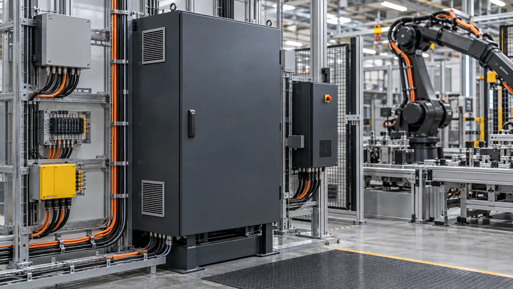
Allow for welding screens, fume capture, hot-part handling and maintenance, not only the robot sweep. Route torch services and the welding return path deliberately. Confirm the welder interface, external axes, cleaning station and restart sequence with the offered controller. Test the agreed joints and inspection method on representative parts before fixing the production settings.
| Selection factor | Information to specify |
|---|---|
| Joint and material | Drawings, thickness, weld size, incoming gap and the specified inspection method. |
| Torch and fixture | Tool mass, neck geometry, clamp locations, access angle and changeover method. |
| Process and sensing | Power source, wire, gas, seam location/tracking and controller interfaces. |
| Production sequence | Loading, clamping, weld order, cooling, inspection and unloading as a complete cycle. |
From the part to the equipment package
- 01Define joints and fit-up
- 02Locate and clamp the part
- 03Check torch paths and motion
- 04Set the welding package
- 05Test welds and the full cycle
Tooling, interfaces and service access

Product and ordering questions
01What are the applications of Steel Truss Robotic Welding Lines?+
Steel truss robotic welding lines combine long-part support, joint fixtures and robot travel for tubular trusses or Bailey-panel-style lattice assemblies. The layout follows node geometry, member variation and the access needed to weld and unload the complete assembly.
02Does robot repeatability establish weld quality?+
Robot repeatability describes a motion characteristic, not the finished weld. Joint preparation, fixture location, wire, gas, process settings, heat sequence and part variation also matter. Agree the sample parts, weld inspection and acceptance criteria for the actual application rather than translating a robot tolerance into a weld-quality promise.
03What should I consider when choosing Steel Truss Robotic Welding Lines?+
Identify every chord-to-brace joint and the clamps near it. Define tack condition, weld sequence, support positions and dimensional inspection after unclamping. A long rail does not by itself solve access to the far side of a node or control weld distortion.
04What should the equipment package include?+
Identify the selected equipment and separate the following packages: robot and controller, welding equipment, fixture and cell. State which accessories, controls, installation, programming and commissioning are included. This makes equipment-only and integrated proposals comparable without assuming identical supply scope.
05How can I request a quotation for Steel Truss Robotic Welding Lines?+
Send the required model or arrangement, quantity and destination, plus drawings, thickness, weld size, incoming gap and the specified inspection method; tool mass, neck geometry, clamp locations, access angle and changeover method. Add photographs or drawings and identify existing equipment. TubeFrame can then discuss model sourcing, configuration and partner-supported integration as separately defined work packages.
Specify your next equipment package
Send the model or configuration, drawings, quantity and destination. We will discuss equipment sourcing, technical interfaces and any integration work required for your application.